Tighter, better‑insulated buildings slash energy bills—but they also trap moisture. Nationwide insurance data shows condensation‑related claims up 38 % since 2018, and CSIRO research links hidden mould to a 28 % rise in asthma flare‑ups. NCC 2025 responds with the most stringent moisture‑control provisions Australia has seen.
NCC 2025: What’s New?
Code Section
Key Requirement
Who’s Affected
Part F6—Condensation Management
Mandatory vapour‑permeable sarking (min. Class 4) to cold side of framed walls in CZ 6–8
Class 1, 2 & 4 dwellings
Part J1.6—Thermal Breaks & Bridging
Max 0.5 W/m·K linear thermal bridge at wall–roof junctions
Class 2–9 buildings
Verification Method F6V1
Hygrothermal modelling (e.g., WUFI) required for assemblies outside Deemed‑to‑Satisfy
All classes
New DTS Detail
20 mm drained cavity behind cladding in climate zones 6–8
All classes
Tip: If you deviate from DTS, you must submit a hygrothermal report showing ≤ 80 % relative humidity for > 30 days/yr inside the assembly.
Top Condensation Risk Factors
Reverse Vapour Drives in mixed‑mode buildings
Internal Moisture Loads from bathrooms & kitchens
Thermal Bridging at steel studs & balconies
Air Leakage carrying warm moist air into cold cavities
Incorrect Membrane Class—vapour barrier on the wrong side
6 Proven Design Strategies & Typical Costs
Strategy
CapEx Premium (AU$/m² wall)
Moisture Risk Reduction
NCC 2025 Alignment
Class 4 permeable sarking + taped seams
8–12
60–70 %
DTS Part F6
Smart vapour retarder (variable perm)
15–20
70–80 %
Performance Path
Continuous airtightness layer (≤ 3 ACH₅₀)
5–9
40–60 %
Part J1.3
Thermally broken steel studs
18–25
25–40 %
Part J1.6
HRV system (75 % heat recovery)
45–65/m² floor
50–65 %
Part F6 Note 4
WUFI hygrothermal modelling
0.9–1.5/m² GFA
Validation
F6V1
Design Workflow for Compliance
Climate + Use Analysis – Identify internal moisture class and external vapour pressure.
Assembly Selection – Choose DTS wall/roof or flag Performance Solution.
Hygrothermal Modelling – Run WUFI 1D/2D for worst‑case week & annual cycle.
Detailing – Place permeable sarking on cold side; smart retarder on warm side.
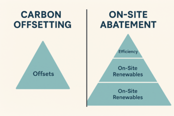
Why This Debate Matters in 2025 Corporate net‑zero pledges are booming, but not all carbon reductions are treated equally. Green Star Buildings v1.1—Australia’s leading sustainability rating—prioritises on‑site abatement over carbon offsets and sets strict eligibility rules for both Read more…
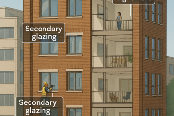
Why Conversions Are Booming in 2025 CBD office vacancies are hovering around 14 %, while Australia’s housing shortfall exceeds 175,000 dwellings. Converting surplus office stock into apartments can be 20–40 % faster than new builds and saves up Read more…
Why Heat‑Island Mitigation Matters in 2025 Australian cities are warming 4–7 °C faster than their rural surrounds. NCC 2025 and many local councils now require urban heat‑island (UHI) mitigation plans for large developments. Green Star Buildings v1.1 offers up Read more…

0 Comments